One essencial accessory for a Table Saw is a Cross Cut Sled. A Cross Cut Sled Is an accessory that allows to make straight cuts and always with the same size, as it supports the piece of wood on both sides of the blade, unlike the accessories that the table saw brings. In addition, it increases the level of safety in the use of the saw, as the hands can be further away from the blade. If we make a search on Youtube we have several tutorials for its construction. But because each table saw model is unique, it is necessary to customize the construction to our model.
Since I had several pieces of wood, mainly 20mm chipboard, that I had bought for use on a shelf, I decided to use it and build the Cross Cut Sled.
Cross Cut Sled
Materials
For the construction of this sled i only use wood leftovers , wood glue and screws.
In addition to the table saw i use an orbital sander and a router. But this aren’t essencial. They were only used for finishing. In addition to these materials, the use of clamps and screwdriver make the process simpler and faster.
In this article it will be launch the first tutorial in video blog.
One technology that came up with 3D printers was 3D scanning. There are several equipment that allow you to do this, some more accessible, some less. Some time ago, BQ launched a model called Ciclops.
BQ Ciclop
It’s a relatively affordable 3D scanner just like others on the market. However it has a unique particularity. BQ, in addition to launching the scanner for sale as a kit, also made available the software, the specifications of each component and the design of the parts for printing. That is, we can buy the complete kit from BQ or we can buy and print the various components and build the scanner.
One of the features of the scanner is to use a Logitech camera to capture, such as the Logitech C270. Since it is a common webcam, it can be replaced by another. In my case I will use a Logitech C250 that was stopped at home. It has the same specifications being the only difference the physical format.
Logitech C250*Logitech C270*
Scanner Material
Below is the BOM (Bill of Materials) of the scanner. Some components are easy to find, others aren’t.
Electronics
Description
Quantity
Price in €
Supplier
Obs.
ZUM BT328 rev2 + Stepstick Drivers A49988 + ZUM SCAN Shield
The printed parts were downloaded from here and printed on the Prusa I3.
Adaptations
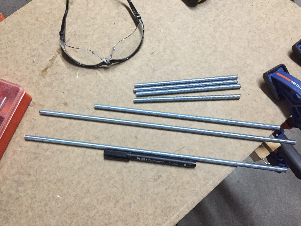
In relation to the threaded shafts, they were bought in AKI and cut to size. They sell in segments of 1 meter.
The ZUM BT328 rev2, the ZUM Scan Shield and the Stepstick are only sold in a pack along with the hardware and the camera on BQ. As I was not interested in buying the complete kit, since I already had parts, I purchased an Aliexpress kit consisting of an Arduino Uno, a Stepstick and a Zum Scan clone for € 26. The difference in operation is in the Bluetooth module. The ZUM BT382 has built-in Bluetooth while the Arduino doesn’t.
The acrylic base was replaced by an MDF disc of 8mm with 200mm diameter.
The calibration standard was printed and glued on a 3mm acrylic panel. You can download the pattern and design from the acrylic panel here.
The Logitech C270 camera was replaced with a Logitech C250 that i already had.
Assembly
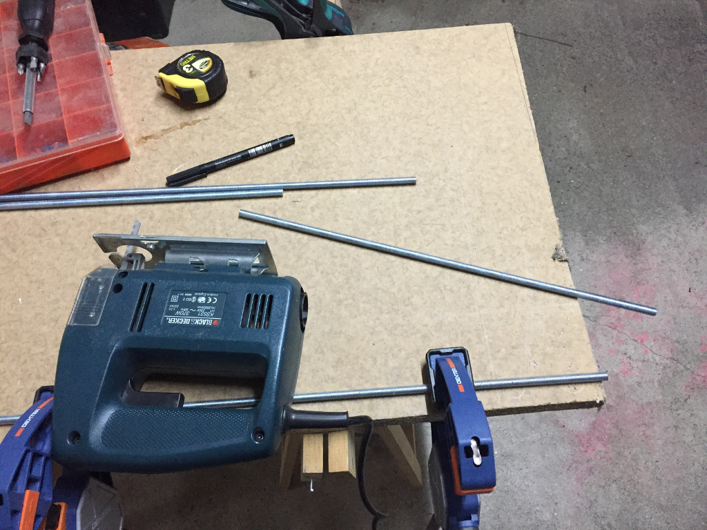
For the cutting of the shafts with the requested measure was used a jigsaw with a metal blade. An angle grinder with a metal cutting disk may also be used but in this case care must be taken with the incandescent filings.
[slideshow_deploy id=’641′]
After the shafts have the right measurements, we begin the assembly of the scanner. BQ offers tutorials of each step. They can be downloaded here.
As the manuals are well documented I will only indicate small changes made.
The brackets that are made available for the lasers are adapted to the lasers that the BQ uses. As the acquired lasers have larger diameter, it was necessary to redesign the supports to accommodate them. This new support can be downloaded to my Thingiverse account (find the link in the top menu).
Some assembly steps
Platform and motor assembly
Motor and platform
Shaft assembly
Main shaftsArm shafts
Electronics assembly
LaserArduino
After the scanner is assembled it’s necessary to download the firmware and load it to the Arduino.
This can be downloaded to GitHub from BQLabs (link). In my case, even using another camera model didn’t change any parameters. To load the firmware for the Arduino we use the Arduino IDE. Open the file horus-fw.ino choose the board in the “Tools-> Board” menu and load the Upload button (the button with an arrow to the right.
After this process we download the scanning software (Horus) and configure it. This can be downloaded from BQ transfer area. There are versions for Windows, Linux and OS X (Mac).
BQ once again provided a manual with the various options and steps to be performed in the software. As the manual is detailed, I will only indicate topics and notes to the process.
Calibration
The first step is to calibrate the scanner. For this we can initially use the “Wizard Mode” and then “Advanced Calibration”.
In “Wizard Mode”, the software will only perform some basic tests, such as verifying that the calibration pattern is detected, checking the lasers (the line they form must be vertical and sharp).
NOTE: One factor that greatly influences calibration and scanning is light. It is recommended that the scanner be in a well-lit location but not receive light directly.
In “Advanced Calibration” Horus allows you to perform several steps such as adjusting the light conditions of the camera, checking the alignment of the lasers, checking the detection of the pattern.
In this mode you must calibrate the scanner in the following order:
1 – Intrinsic values
This option calibrates the pattern in several positions. It takes ten catches to calibrate. These captures should be done with the pattern in several positions but taking care that the bars of the image are green. If they are red, the scanner has not detected the pattern.
2 – Triangulation of lasers
This is one of the most important calibration processes and one of the most complex steps. It determines the distance, position and inclination of the lasers towards the camera. After the process Horus presents the values he has captured. These values must be 0.1 or less. If they are larger, they compromise the scan. This process is strongly influenced by the focus of the lasers and, mainly, by the luminosity. It is highly recommended a bright environment but no direct light. In my case, I have only achieved an acceptable calibration by placing the scanner in a controlled environment (inside a photo light box with uniform diffused illumination at the top and adjusting the following parameters in the camera settings:
Bright: 150
Contrast: 38
Saturation: 39
Exposition: 65
Ciclop in Soft box
These values were achieved through attempts. After posting questions on the Ciclop BQ discussion group on Google (insert link), they indicated values used with the Logitech C270. Based on these values I have been adjusting to get the ideas for myself.
These values, while ideal for me, may not be for other cases. It all depends on the lighting used.
Values for the Logitech C270:
Bright: 185
Contrast: 37
Saturation: 39
Exposition: 48
These values are indicated for use under ambient light or with fluorescent lamps with a temperature around 6500K.
3 – Extrinsic parameters
This calibration step will detect the position and rotation of the disc relative to the camera. This is another very important step in calibration.
Digitalization
After this calibration steps we can proceed to the scanning. For this we choose in the upper right corner of the Horus “Scan Area”.
Here we can choose whether we want a scan only of the shape of the object or also of the texture, how many lasers we want to use, the parameters of the rotation of the platform, the parameters of image acquisition (they should be the same ones used in the calibration) and define the cloud of points .
Point Cloud
To create the cloud of points, we specify the diameter and height of the object to be scanned in order to minimize the capture of unwanted objects (noise).
After scanning, the object must be treated in a 3D rendering program. BQ provides a simple tutorial of this process on MeshLab and CloudCompare on their page. In addition to these two you can use any one that imports .ply files.
One of the places where I collaborate is at FabLab Castelo Branco. Not as an employee but helping when needed. The latest help was preparing a mUVe 3D DLP 1.1 printer.
A DLP printer is a 3D printer that, instead of melting filaments and layering them, uses a proprietary resin that is cured over a given wavelength. This wavelength can be generated through several means, being the most common by laser or through a DLP projector as is the case of this mUVe.
mUVe 3D DLP
Assembly
This printer has been purchased completely disassembled, requiring the on-site assembly. Instructions for assembly are on the manufacturer’s page (http://www.muve3d.net/press/) and can be downloaded here. Before mounting the electronic part, it is necessary to load the mUVe firmware for the Arduino to function correctly. This firmware can be downloaded here.
To carry out this loading, you need a computer with Arduino IDE installed (it can be downloaded free here).
After downloading the firmware, we decompress it and it is necessary to change an option in your configuration.
Open the file “Marlin.ino” in the Arduino IDE and in the “Configuration.h” file, we uncomment the line removing “//” from the start:
#define DEFAULT_AXIS_STEPS_PER_UNIT   {36.36,36.36,640,640}
// default settings for for mUVe 1-1.1
Next we commented the line placing “//” at the beginning:
#define DEFAULT_AXIS_STEPS_PER_UNIT   {36.36,36.36,400,400}
//default settings for for mUVe 1.5 or if you have the leadscrew upgrade
These two lines indicate which printer version we are using. By default, version 1.5 is selected. In our case, the version is 1.1.
The difference between the versions is the type of threaded shaft. If we loaded the firmware with the version 1.5 chosen, the distances traveled in the Z axis did not coincide with the real ones. In this case, when you indicated that the printer lifted the Z-axis by 100mm, it only ran 60mm.
Next we load the firmware for the Arduino. Before connecting the Arduino we have to install the specific drivers for this one. They can be downloaded here.
We connect the Arduino to the computer and chose the following options:
In the “tools” menu, in the “board” option we choose “Arduino / Genuine Mega or Mega 2560”.
In the port option we choose the port where the Arduino is connected.
Next we load the firmware for the Arduino by pressing the button with the arrow. The Arduino software will check for errors in the code and compile and then load the firmware for the Arduino.
Upload button
Software configuration
There are two options for using mUVe:
Through the software “Creation Workshop”. This software requires a computer or laptop with a second video output to connect to the projector and it is necessary to acquire a license. You can test it for 30 days by downloading it from the manufacturer’s website (https://datatree3d.com/software/)
Through NanoDLP. This is a distribution for Raspberry Pi 2 or 3. You need a Raspberry Pi 2 or 3, a microsd card with at least 2 gb, an HDMI-> VGA adapter and a transformer for the Raspberry Pi. NanoDLP has the advantage of being free, and only need to buy Raspberry Pi and its accessory. It can be downloaded here (http://www.nanodlp.com/)
Due to the limited budget, I chose to use NanoDLP.
The installation process of this is extremely simple. The manufacturer has all the installation steps on the site. You can follow these steps here (http://www.nanodlp.com/download/). If you are not comfortable with the command line, I advise you to use “Simple Installation”.
Next we need to configure the NanoDLP. For this mUVe provided a tutorial step by step. You can download the tutorial here.
Keep an eye on all the steps, as they just fail one to not work properly (I speak from experience :)).
Tray preparation
The mUVe had a sheet of silicone to place on the bottom of the glass tray, so the cured resin layers did not attach to it. After several attempts, I couldn’t use them, because it always passes resin between the sheet and the glass and heals there, instead of at the top of the sheet.
mUVe 3D DLP Vat with silicon sheet
Fortunately it also had a liquid silicone called QSIL216. This comes in two bottles, one being the silicone and the other the catalyst to cure it. This silicone is poured into the tray and when cured, creates a film that prevents resin from reaching the glass. As I was told in a workshop on the 2016 edition of Lisbon Maker Faire (Polymer Conversion from Silicone Molds) given by Ricardo Pereira, “The only thing that sticks to silicone is silicone.”
QSil 2016 Preparation
Tray with QSil 2016
The preparation process consists of mixing the components and allowing them to cure. mUVe also has a tutorial on how to apply on the board that you can check here.
NanoDLP Configuration
To configure nanoDLP for mUVE 1.0 DLP we need to change two sections, the “Hardware Setup” inside the “Setup” section and add a print profile to the “Printer profiles” section. All others may be left with the source options.
Hardware Setup Section
In this section we will configure the connection of the nanoDLP to the Arduino that controls the mUVe, GCode for mUVe startup, print start, print summary and end of print, projector resolution and resin platform and engine characteristics. The GCode are commands for movement of the engines that Arduino understands. For a more detailed query, you can consult the Reprap page where all Gcode (http://reprap.org/wiki/G-code)
Next are the options for communication with the Arduino, the Gcode required and the resolution of the projector:
Hardware configuration – part 1Hardware configuration – part 2
Finally we have the characteristics of the resin platform and the motors:
Hardware configuration – part 3Hardware configuration – part 4
There are more options to set if there is a shutter to cover the projector lens between each exposure, if the projector is being controlled by the nanoDLP through the serial port (if any), and if there is a control lcd, camera to capture the impression and control buttons.
Profile Section
The addition of a new profile is the section that will control the printing itself. This is where we set the exposure time of the first and the remaining layers, how many initial layers there are, what is the print resolution and Gcode to run before and after each layer is printed. These are the most important options in this section. There are others but they are not so relevant.
The options within the category “Burn-in layers” refer to the first layers. The number of layers is set in the “Number of Layers” option. Options within the “Normal Layers” category refer to the remaining layers. In these two categories, the most critical options are:
X / Y resolution: resolution that will be used in printing. There is a formula for calculating this resolution. This calculation is done when the projector is calibrated and focused (next section);
Cure Time: is the exposure time of each layer in the light of the projector. These values vary from projector to projector and depending on the type of resin used. In this case a Viesonic 7820 HD Projector is used with MakerJuice G + resin. To set the right values must be by trial-error.
Printing profile – part 1Printing profile – part 2Printing profile – part 3
Projector calibration
To calibrate the projector, place a white sheet on the bottom of the tray and in the “Projector Calibration” section, select the “Projector Boundaries” option. This option will project the limits of the projector image. These limits must be within the area of the board and should occupy the largest possible area. The more area occupied by the image the larger the objects can be printed. If the projection exceeds the limits of the tray, the image should be resized, via the adjustment ring of the projector, if present, or through the distance from the projector to the tray.
Next we chose the option “Projector Calibration Image”. This option will project a grid. This grid should be completely focused on the sheet of paper. If isn’t the impression will have problems and be incorrect. After the image is focus, we check the resolution that will be used. For this we measure one side of the image and then use the following formula:
Distance measured in mm / Projector resolution on this axis = final resolution
Note that the final resolution is given in mm and the nanoDLP sets in microns. To carry out the conversion we multiply the final value by 1000.
In my case, the larger side was 125mm and the resolution on that side was 1024.
125/1024 = 0.122
Multiplying by 1000 we have 122 microns.
Printing
After everything is ready we can start printing. We can use an .STL or .SVG file.
We put the resin in the tray (in this case I’m using MakerJuice G + Red). Then load the file into NanoDLP and started the printing process. If all goes well at the end of time the object they should be printed. Attention that this is a time consuming process. A 2.5cm Marvin took 3 hours to print.
[slideshow_deploy id=’597′]
If you want to deepen the knowledge of the nanoDLP / mUVe sets there is a configuration and user manual on the muve3d page. You can check it here
In the third part of this tutorial we are starting the configuration process.
If you want to check part 2, where we started the assembly, you can do it on here.
The QBrain have multiple configuration parameters but, in this case, we only will see two: teach the QBrain the throttle minimum and maximum values and what type of battery is used.
In the second part of this tutorial will proceed to the assembly of the Quadcopter .
If you want to see part 1, which are the various components shown , you can do it here.
Before beginning assembly it’s necessary to do the welding operations. If you have no experience in this area, ask for help to avoid accidents. It’s necessary to weld the bullets to the motor terminals and weld the XT60 plug to QBrain terminals. ATTENTION TO POLARITY. The red cable QBrain must match the red battery cable.
After the welds begins the frame assembly. For the frame in question, there is a manual that can be downloaded here. During assembly it’s necessary to perform an extra step to install QBrain. In step 8, before screwing the body, it is necessary to put between the plates, in the space formed by the arms, the QBrain. Prior to the screw, you must take note of all the information that is on the body.
Flightboard connections
The flightboard has several connectors. The following table precedes a brief explanation of each connector block :
Pins
Description
I2C
I2C connection. For a GPS.
UART
Serial connection. Fro a bluetooth module to transmit telemetry
FDTI
FDTI cable connection. Connects the flightboard to the computer for configuration.
Pin with names -, + , D2,…
Connections for the receiver
Pin with names 12, 8, 9, …
Connections for the motors. The pins A0,A1 e A2 are used to conect a Gimbal servo.
Flightboard
Connect the QBrain to the Flightboard
To connect the QBrain to the flighboard is necessary to identify, in the QBrain, which is the motor that can connect to each cable and, in the flighboard, which pin controls each motor. The first information is printed at the top of QBrain. The second can be found on the MultiWii site ( http://www.multiwii.com/connecting-elements ). Following this information the connections are:
QBrain
Flighboard
Motor 1 – Red cable
Pin 11
Motor 2 – Orange cable
Pin 9
Motor 3 – White cable
Pin 10
Motor 4 – brown cable
Pin 3
In the connections it is necessary to pay attention to the pin position on the flighboard. The outer row of pins is the negative pole, the middle one is positive and the inner is the control. In QBrain there are two cables for motors. One of the cables has a plug, and the other has three. The one who has only one plug transmits the signal to each engine. The one with three also powers the flightboard.
Connect the flightboard to the receiver
For connect the receiver to flightboard it’s necessary to identify each channel. In the case of this set – radio+ receiver – the channel’s are:
Channel
Function
Channel 1
Roll
Channel 2
Pitch
Channel 3
Throttle
Channel 4
Yaw
In the flightboard cable is:
Pin
Description
–
Powers theflightboard. Ground
+
Powers the flightboard. Positive
D2
Throttle
D4
Aileron ( Roll )
D5
Elevator ( Pitch )
D6
Rudder ( Yaw )
D7
Aux 1
D8
Aux 2 ( It’s necessary to define this pin on the Multiwii configuration )
These connections are made with the following cables:
Cables
This flightboard allows to power the receiver. Therefore, we will use the cable that only has two plugs for the first connection. On one side we connect the receiver and the throttle connection; in the other connect,in the flightboard, pins ‘-’, ‘+’ and ‘D2’. It’s necessary to note what is the signal pin and what is the power pin, both at the receiver and flightboard.
Next connect the two cables having a plug at one side and three on the other. The side has only one plug connects to the flightboard and the three plugs connects to the receiver. The first cable connects to the pins ‘D4’, ‘D5’ , and ‘D6’ and the second in ‘D7’ and ‘D8’. In the receiver side the cables are connected according to previous table.
Calibrate propellers
Before we set up the blades it is necessary to calibrate them. The calibration consists in balance the propellers so as to have substantially the same weight on both sides. For this we can use a commercial equipment or build one of ours. In my case I print one, according to my needs. The template can be downloaded in my Thingiverse account ( find the link in the top menu ).
I use, for example, a screwdriver to support the propeller on the support and verify if it’s balanced. To do this check, put the propeller horizontally. If it remains in position, it is balanced . Otherwise, the descending side is heavier, therefore, need to proceed to a compensation. To do this, place small pieces of adhesive tape in the opposite paddle so we increase the weight. After each placement tape repeat the verification process till it’s balanced.
Propeller calibratorPropeller calibrated
In the third part we are going to configure the QBrain.
For some time now I have been getting a number of parts for the assembly of a X Quadcopter. Following the OOZ Labs tutorial i was gathering all the parts.
One of the things we wanted to acquire, for some time, was a 3D printer. But taking into account the prices and maintenance I decided to assemble my own. I decided to assemble it because the cost is lower and when it is necessary to perform maintenance, i know exactly what part purchase, where to buy and how to replace it.
A few months ago i’ve presented a workshop about Arduino and decided to build a simple meteorological station. The station measure the temperature and humidity level, showing the values on a LCD and on a visual indicator. This indicator as three leds: one blue, one green and one red.
One of my projects is to automate a LEGO City, especially the train section. For that i need a place to save all the information. Initially choose a SQL database (MySQL), but as necessary to create custom tables for each case and create relations. But as i didn’t know what information was supplied by the City and i would need a communication protocol ( i’ll use MQTT. In the future i’ll write a tutorial how to use it) i choose a NoSQl database, MongoDB.
We use cookies on our website to give you the most relevant experience by remembering your preferences and repeat visits. By clicking “Accept”, you consent to the use of ALL the cookies.
This website uses cookies to improve your experience while you navigate through the website. Out of these, the cookies that are categorized as necessary are stored on your browser as they are essential for the working of basic functionalities of the website. We also use third-party cookies that help us analyze and understand how you use this website. These cookies will be stored in your browser only with your consent. You also have the option to opt-out of these cookies. But opting out of some of these cookies may affect your browsing experience.
Necessary cookies are absolutely essential for the website to function properly. This category only includes cookies that ensures basic functionalities and security features of the website. These cookies do not store any personal information.
Any cookies that may not be particularly necessary for the website to function and is used specifically to collect user personal data via analytics, ads, other embedded contents are termed as non-necessary cookies. It is mandatory to procure user consent prior to running these cookies on your website.