
One of the problems that exist in the Prusa i3 3D printers is the open space and air circulation. This open space makes it difficult to warm the table, prevent it from reaching higher temperatures and makes it more difficult to maintain a constant temperature, which can compromise printing. If the temperature falls below a certain value, the part can be released from the table.
To avoid this situation and print on materials that require a higher table temperature (eg ABS) i decided to build a protection similar to the Ultimaker printers for the Prusa i3 Hephestos already builded. And following the innovations of Ultimaker 3, I choose to put a Raspberry Pi with a camera running the OctoPi (operating system for control 3D printers) that allows to control the printer, adds wireless connectivity, allows remote monitoring of the printing process and creates a timelapse of this, in addition to adding lighting through led tapes. For this I created a stand in MDF and acrylic sides.
Materials needed
For this project it was necessary:
- 8mm MDF
- Acrylic
- Wood glue
- M3x12 Screws
- M3 nuts
- M4x14 Screws
- M4 nuts
- M4 Washers
- 12V Led Strip
- Union Boxes
- Terminals
- Electric cable
- Female socket
- Illuminated button
- Vinyl
- Primary
- White paint
- Varnish
- 12V 20 A Power Supply
- Raspberry Pi 2
- Raspberry Pi Webcam
- 16GB MicroSD Card
- 5V Power Supply
And used the following tools:
- Table saw
- Orbital sander
- Nail gun
- Jigsaw
- Clamps
- Laser cutting machine
- Vinyl Cutter
- Paint Stands
- Tape measure
- Square
Base
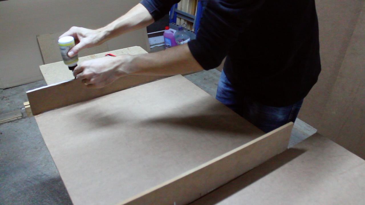
First it was necessary to create the base. This was built in 8mm MDF. It was designed to allow storage of all printer power, Raspberry Pi and lighting.
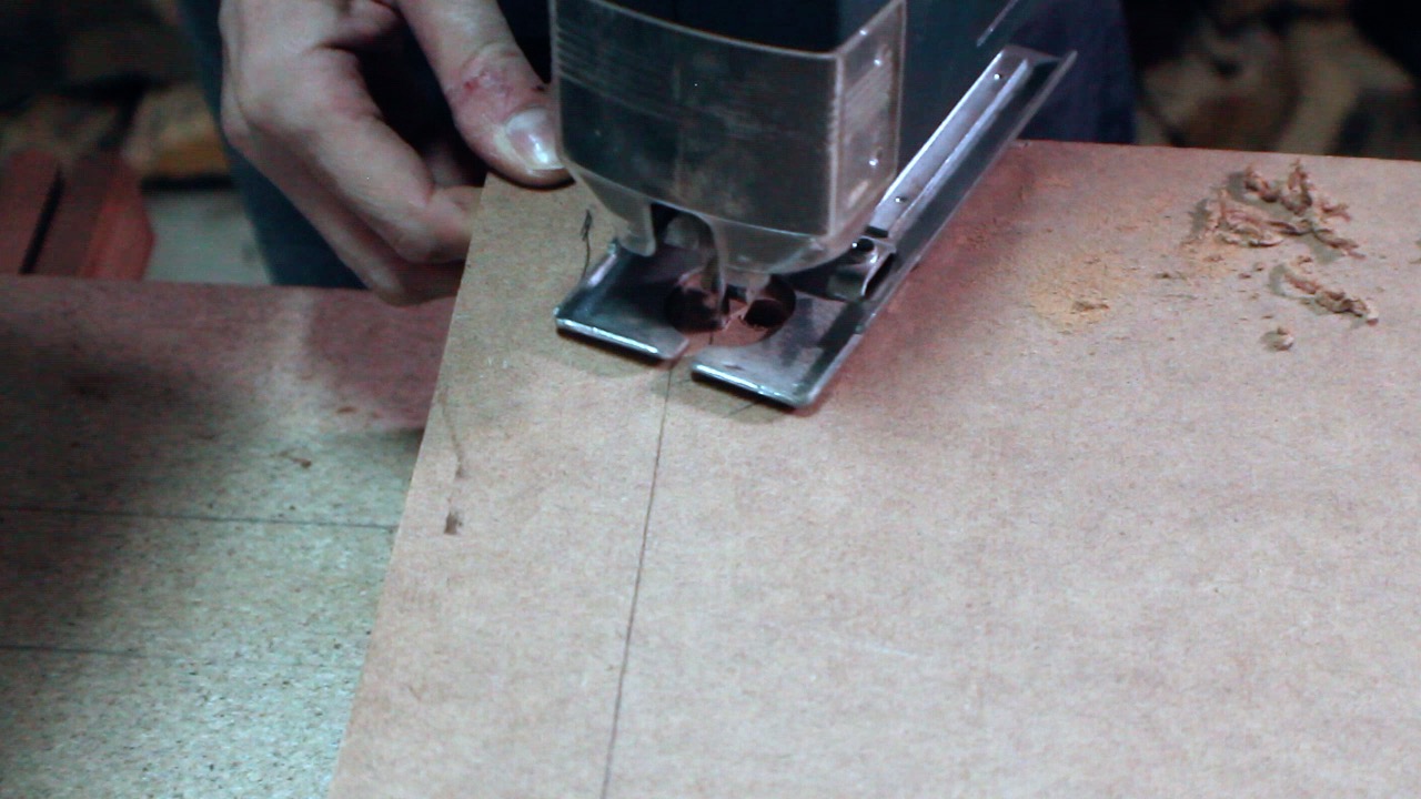
The top, bottom and sides were cut on the table saw, followed by the assembly process. These were glued with wood glue, using the nail gun and clamps to secure them while gluing. It could only use clamps, but implied having to glue completely before moving forward (about 24 hours). With the nails it was enough to allow a few hours of glue to dry as the work progressed.
Then the cable runs were created to feed the printer and Raspberry Pi.
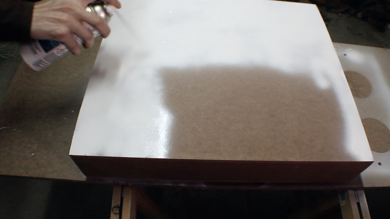
After being glued together, everything was sanded in order to remove possible traces of glue, edges and prepare the surfaces for painting.
A primer coat was applied to seal the MDF and, after drying, white paint and a coat of varnish were applied to protect.
Acrylic side panels
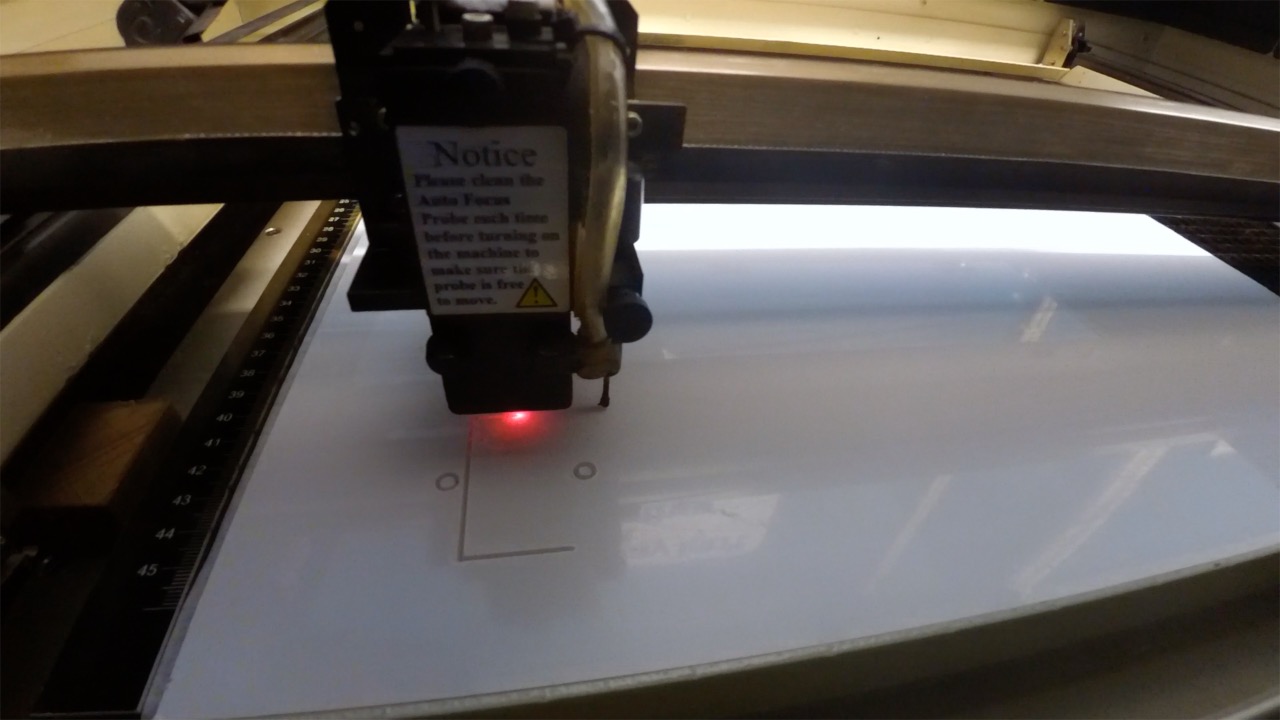
For the sides was used 5mm opal acrylic in order to support its weight. These were design in Adobe Illustrator and cut in a laser cutter. In the case of the sides only the drill holes were cut for screws. In the rear, in addition to the drill holes of the screws was cut the entrance to the electrical outlet. At the front and top was also cut off the accesses to the printer.
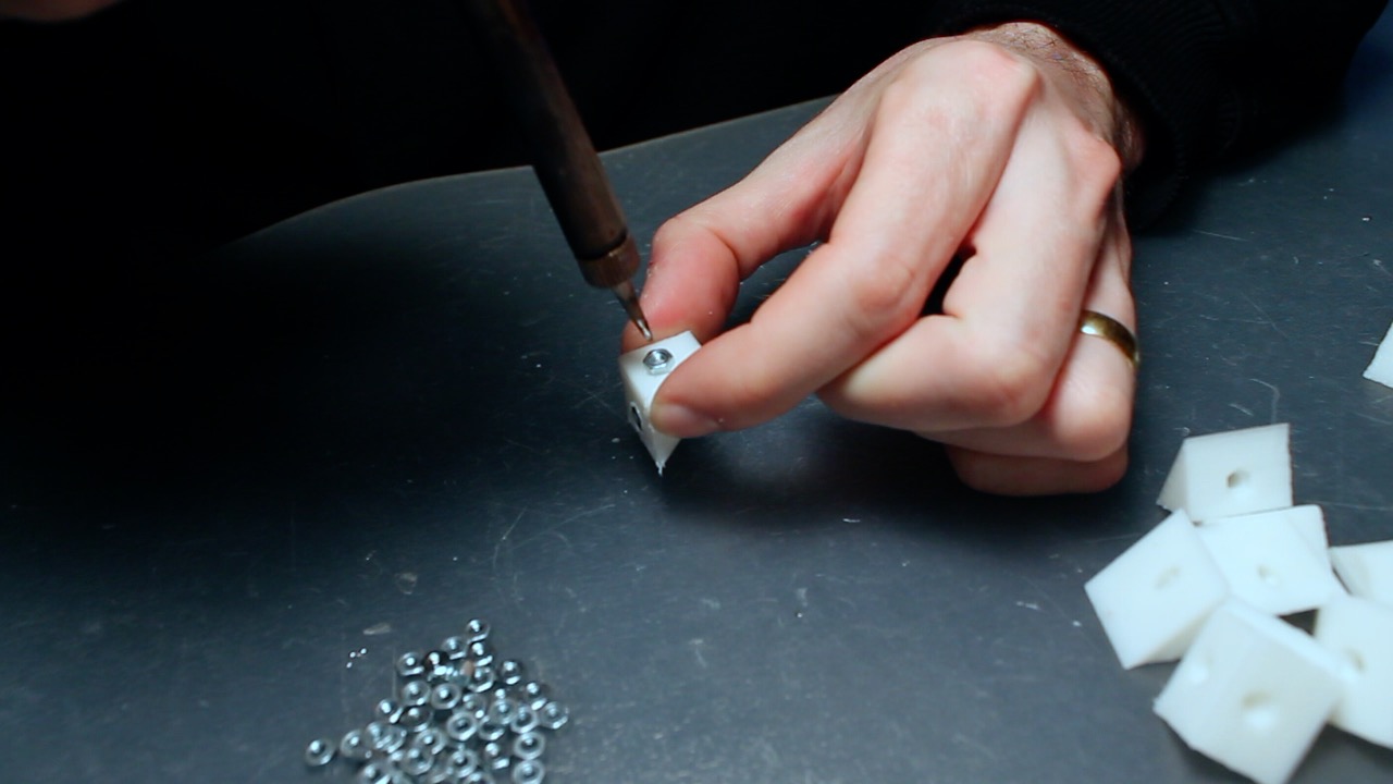
For the assembly of the sides were designed and printed unions in PLA (available in my Thingiverse account). After printing, an M3 nut was embedded using a soldering iron.
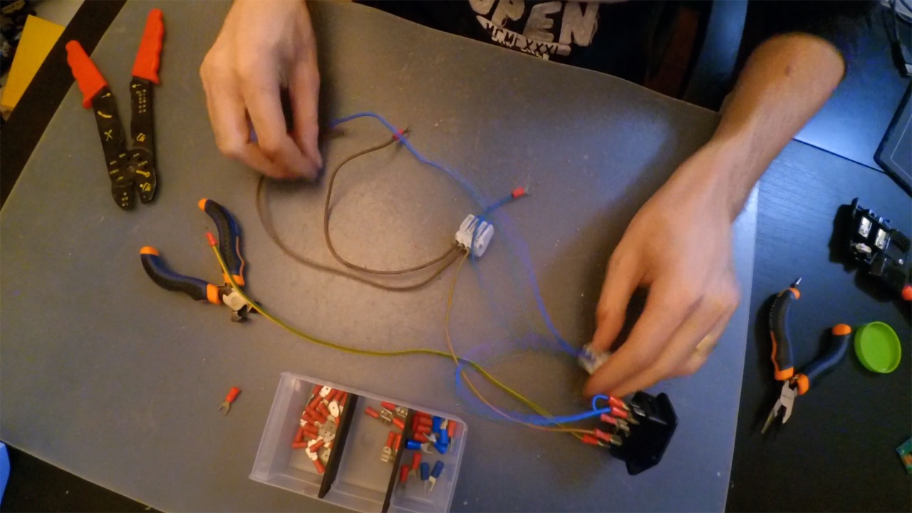
It was then created the electrical structure that will power the printer and the Raspberry Pi. Terminals were used for connection the printer’s external outlet and 12V power supply, and a female jack to connect the Raspberry Pi transformer.
Vinyl
The side logo was created in Adobe Illustrator and cut into a vinyl cutter.
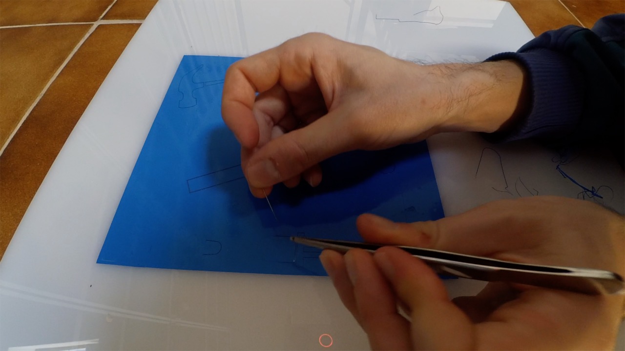
For the application of this, was placed painter tape on the surface and the rear protective film was removed. After this, it was placed in the acrylic, in the previously marked places.
After being fixed, the painter’s tape was removed very carefully to not rip the vinyl. Then, with the tip of a needle, the excess vinyl was removed, so that only the logo remain.
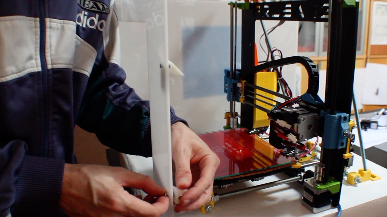
Side mounting
On the front and rear was installed the electrical part (button and power).
Then they were mounted on place, fixed with the respective supports, installed the led illumination and the power supply with the respective connections.In the end the structure was fixed to the base.
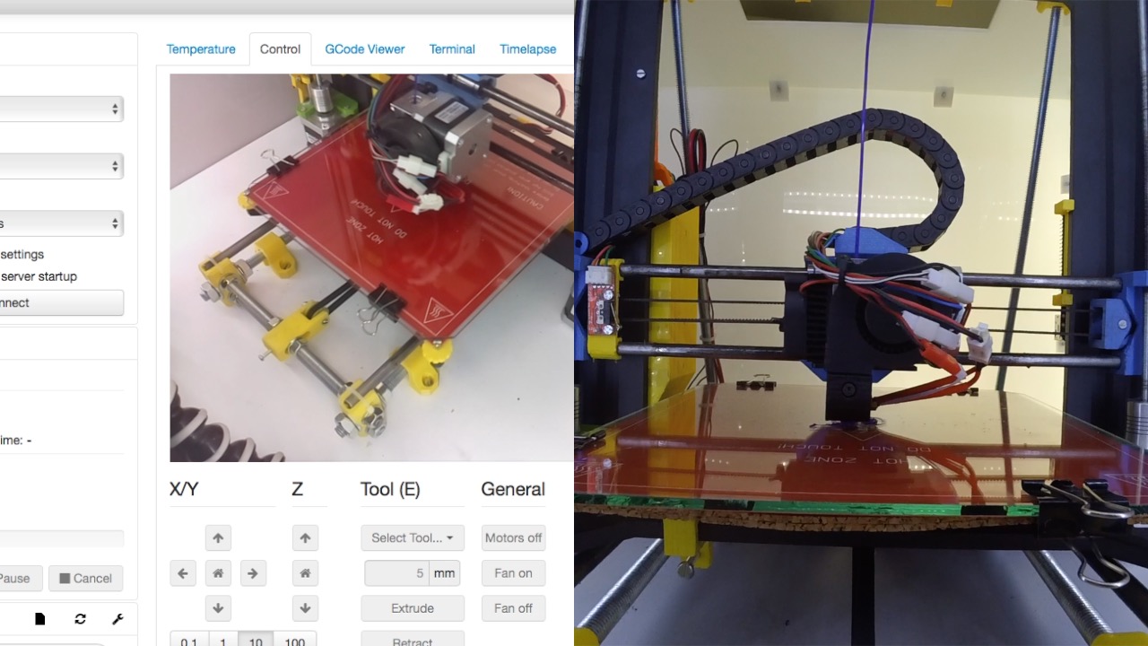
OctoPi Installation
Was installed the OctoPi on a Raspberry Pi 2 and with the base configuration. Because OctoPi supports a camera, a custom mount was designed for installation at the top of the enclosure. After printed, the camera was installed in this and the set was installed in the interior top with the Raspberry Pi fixed to the structure of the Prusa.
Finally, OctoPi and Illumination were tested.
Comments are closed.