

For some time now I wanted to start automating parts of the house. Although several parties are already planned, I decided to start with the aquarium.
Currently the aquarium has two analog timers to control lighting and water filtration. The problem is that whenever there is a light fault, the timers change the lighting and filtering times.
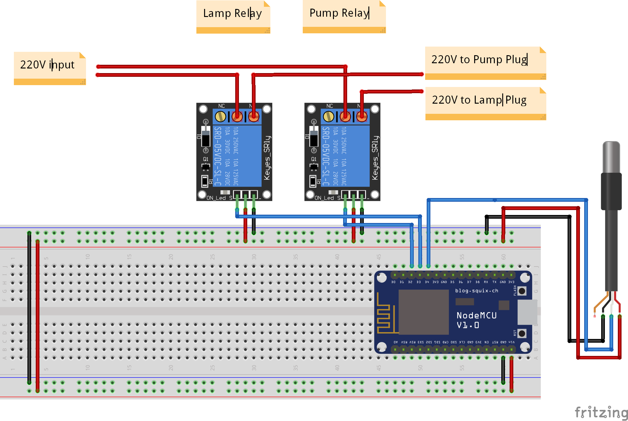
To solve this problem, I decided to install a nodeMCU module, which receives water temperature data through a probe, controls lighting and filtering through a relay, and communicates with the Raspberry Pi that controls all IoT (Internet of Things) through MQTT (Message Queuing Telemetry Transport) messages.
Box
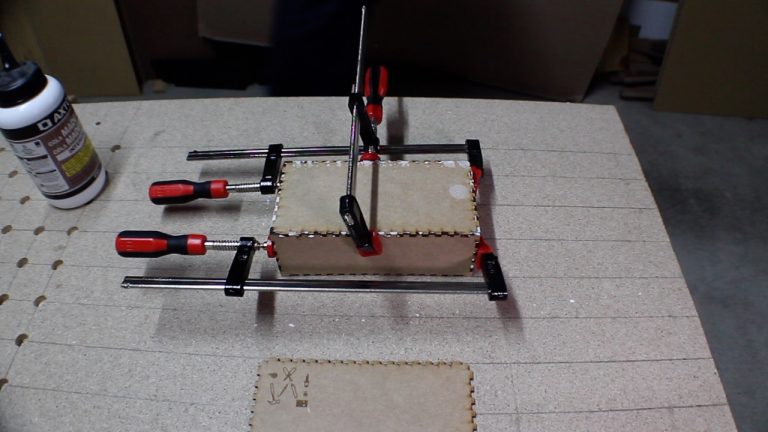
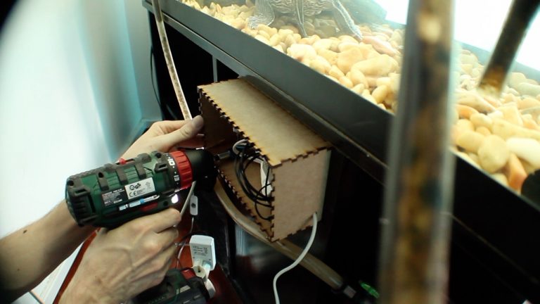
Initially i’ve designed a box in Adobe Illustrator able to accommodate all the components and cut it in a laser cutter.
It was then glued with wood glue and place staples to continue de building process while drying the glue.
Material needed:
For this project was needed:
- One nodeMCU
- One Relay
- One waterproof temperature probe
- MDF
- Electric cables
- Electric female plugs
- Electric cable wire connectors
- Solder
- Flux
- Heat Shrink Tubing
- Female SIL Socket Row Strip PCB Connector
- Prototype Circuit Board
And used the following tools:
- Laser cutting machine
- Wood screws
- Wood glue
- Clamps
- Soldering iron
Electronics
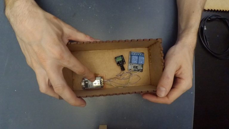
Then it was installed the electronics. A base has been created for the nodeMCU so that it is removable. The respective connections for the temperature probe and the relay were created and the plugs installed.
Code
The nodeMCU has been programmed with the following code:
#include <ESP8266WiFi.h>
#include <OneWire.h>
#include <DallasTemperature.h>
#include <PubSubClient.h>
#include <NTPClient.h>
#include <WiFiUdp.h>

// Define pin numbers
#define ONE_WIRE_BUS D4
#define PumpRelay D2
#define LampRelay D3
#define Temp D4

//Wireless Info
const char* ssid = "<SSID>";
const char* password = "<SSID PASSWORD>";

//MQTT Info
char* LampTopic = "< MQTT LIGHT TOPIC >";
char* PumpTopic = "< MQTT PUMP TOPIC >";
char* TempTopic = "< MQTT TEMP TOPIC >";
const char* server = "< SERVER >";
String clientName = "nodemcu-aquarium";
char message_buff[100];

//NTP Info
WiFiUDP ntpUDP;
NTPClient timeClient(ntpUDP);

int temp=0;
int lamp_mode = 0; //0-auto 1-manual
int pump_mode = 0; //0-auto 1-manual
//Define a OneWire object to communicate
OneWire oneWire(ONE_WIRE_BUS);

DallasTemperature sensors(&oneWire);
DeviceAddress sensor1;

void show_sensor_address(DeviceAddress deviceAddress)
{
 for (uint8_t i = 0; i < 8; i++)
 {
 if (deviceAddress[i] < 16) Serial.print("0");
 Serial.print(deviceAddress[i], HEX);
 }
}

//Pump Control
void pump_off(){
 digitalWrite(PumpRelay, LOW);
}

void pump_on(){
 digitalWrite(PumpRelay, HIGH);
}
//Lamp Control
void lamp_off(){
 digitalWrite(LampRelay, LOW);
}

void lamp_on(){
 digitalWrite(LampRelay, HIGH);
}

//CallBack MQTT
void callback(char* topic, byte* payload, unsigned int length) {
 int i = 0;

Serial.println("Message arrived: topic: " + String(topic));
 Serial.println("Length: " + String(length,DEC));

 for(i=0; i<length; i++) {
 message_buff[i] = payload[i];
 }
 message_buff[i] = '\0';

 String msgString = String(message_buff);

 Serial.println("Payload: " + msgString);
 Serial.println(msgString);

if (strcmp(topic,LampTopic)==0) {
 if(msgString == "off"){
 lamp_off();
 lamp_mode = 1;
 }
 else if(msgString == "on"){
 lamp_on();
 lamp_mode = 1;
 }
 if (msgString == "autolamp"){
 Serial.println("auto");
 lamp_mode = 0;
 }
 }

if (strcmp(topic,PumpTopic)==0) {
 if(msgString == "off"){
 pump_off();
 pump_mode = 1;
 }
 else if(msgString == "on"){
 pump_on();
 pump_mode = 1;
 }
 if (msgString == "autopump"){
 Serial.println("auto");
 pump_mode = 0;
 }
 }
}

//Inicialization
WiFiClient wifiClient;
PubSubClient client(server, 1883, callback, wifiClient);

void setup() {
 pinMode(PumpRelay,OUTPUT);
 pinMode(LampRelay,OUTPUT);
 pinMode(Temp,INPUT);
 Serial.begin(115200);
 sensors.begin();
 timeClient.begin();

//Wireless Connection
 WiFi.begin(ssid, password);
 while (WiFi.status() != WL_CONNECTED) {
 delay(500);
 Serial.print(".");
 }
 Serial.println("");
 Serial.println("WiFi connected");
 Serial.println("IP address: ");
 Serial.println(WiFi.localIP());

//MQTT Connection
 if (client.connect((char*) clientName.c_str())) {
 Serial.println("connected: ");
 client.subscribe(PumpTopic);
 client.subscribe(LampTopic);
 }

//Locating sensors
 Serial.println("Locatting sensors...");
 Serial.print("Found ");
 Serial.print(sensors.getDeviceCount(), DEC);
 Serial.println(" sensors.");
 if (!sensors.getAddress(sensor1, 0))
 Serial.println("Sensors not found!");
 Serial.print("Sensor address: ");
 show_sensor_address(sensor1);
}

void autoModePump(){
 timeClient.update();
 if( (timeClient.getHours() >= 9 ) && (timeClient.getHours() < 23) ){
 pump_on();
 }
 else{
 pump_off();
 }

}

void autoModeLamp(){
 timeClient.update();
 if( (timeClient.getHours() >= 12 ) && (timeClient.getHours() < 17) ){
 lamp_on();
 }
 else{
 lamp_off();
 }

}

void loop() {
 client.loop();
 sensors.requestTemperatures();
 temp = sensors.getTempC(sensor1);
 String temperature = String(temp);
 char payload[temperature.length()+1];
 temperature.toCharArray(payload, temperature.length()+1);
 client.publish( TempTopic, payload );
 if(lamp_mode == 0){
 autoModeLamp();
 }
 if(pump_mode == 0){
 autoModePump();
 }
 delay(1000);
}
This code is also available on my GitHub Account ( https://github.com/d4rks70rm/AquariumController ).
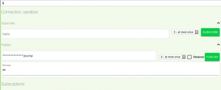
An MQTT topic was defined for each element of the aquarium (lighting, temperature, filtering) in order to communicate.
The system receives three commands for lighting and filtering. ‘On’, ‘Off’ for both and ‘autolamp’ for lighting and ‘autopump’ for filtering. ‘On’ turns on the component and ‘Off’ turns it off. The ‘autopump’ and ‘autolight’ switch the component into automatic mode. In the case of illumination, in automatic mode, it switches on at 12:00h and switches off at 17:00h. The filtering starts at 9:00h and switches off at 11:00h. By default the system starts in automatic mode to stay autonomous in case of failure of communicate with Raspberry Pi that controls all devices.
When starting the nodeMCU, it authenticates in the wifi network and synchronizes its time through an NTP server.
The nodeMCU communicates to Raspberry Pi at each second, through the MQTT topic’s, to transmit the water temperature and receive commands for the lightning and filtering systems.
Assembling
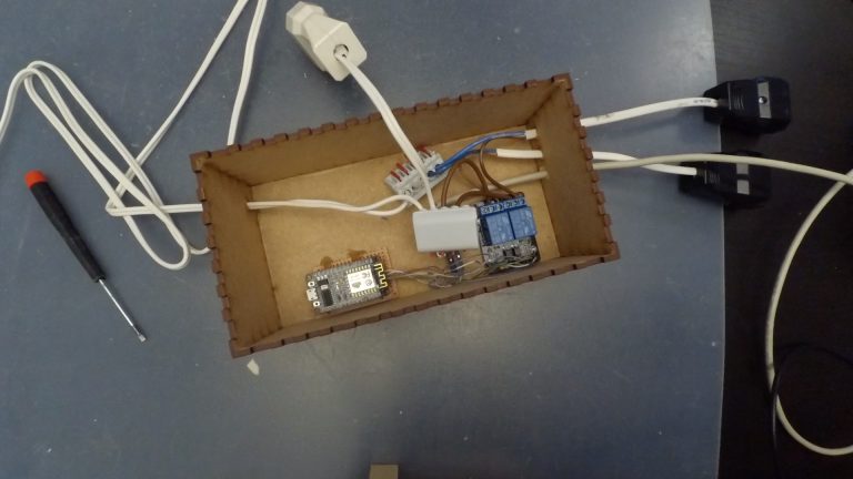
The assembly was installed inside the previously assembled box using hot glue.
The connections have been assembled to power the lighting, the filtering system and the nodeMCU itself.
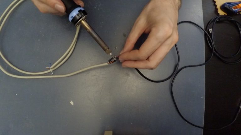
As the probe cable was short, it was necessary to create an extension. This was welded and finished with heat shrink tubing to avoid short circuits. The heat shrink tubing is a protection that, in contact with heat, retracts, staying fixed to the components that we want to protect.
Then the respective wiring was installed.
Installation
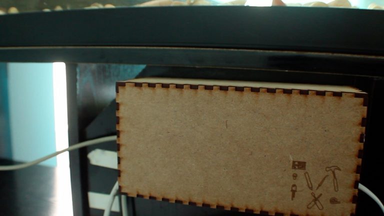
Finally the set was installed in the back of the aquarium using wood screws, the temperature probe was installed inside the aquarium and tested.
Comments are closed.